Nintendo NES
Mainboard Revisions (NTSC)
PCB revisions run from NES-CPU-01 to -11. Revisions below -05 will have noticeably poorer video output than later revisions. Revisions -10 and -11 use circuitry to try to defeat the lockout defeaters of the unlicensed cartridges.
NES-CPU-02 - 2A03E/2C02E-0
The original US release of the NES (fewer than 10,000 were made).
- 1985 copyright on PCB
- VRAM and WRAM are NDIP-only
- 3193 Non-A CIC
NES-CPU-03
- Unreleased
NES-CPU-04 - 2A03E/2C02E-0
- 1986 copyright on PCB
- VRAM and WRAM are NDIP-only
- 3193 Non-A or 3193A CIC
- some have a 74HC139 at U3 instead of 74LS139
NES-CPU-05 - 2A03G/2C02G-0
- 1986 copyright on PCB
- VRAM and WRAM are NDIP-only
- 3193A CIC
NES-CPU-06 - 2A03G/2C02G-0
- 1987 copyright on PCB
- VRAM and WRAM are NDIP or DIP
NES-CPU-07 - 2A03G/2C02G-0
- 1987 copyright on PCB
- VRAM and WRAM are NDIP or DIP
NES-CPU-08 - 2A03G/2C02G-0
- 1989 copyright on PCB
- VRAM and WRAM are NDIP or DIP
NES-CPU-09 - 2A03G/2C02G-0 or 2A07/2C07-0
- 1987 copyright on PCB
- VRAM and WRAM are NDIP or DIP
Has one resistor between CIC pin and cart connector to prevent CIC stun attacks
NES-CPU-10 - 2A03G/2C02G
- 1987 copyright on PCB
- VRAM and WRAM are NDIP or DIP
Has two resistors between CIC pins and cart connector to thwart more CIC voltage stun, some later revisions have a diode to nearby GND vias as well to prevent the -5V attack
NES-CPU-11 - 2A03G/2C02G or 2A07[A]/2C07[A]
- 1987 Copyright on PCB
- VRAM and WRAM are NDIP or DIP
Has two resistors and two diodes between CIC pins, cart connector and GND to prevent CIC stun and -5V attacks
Product Sheets
NES Mainboard (NTSC)
Capacitor Guide
Capacitors play a crucial role in maintaining a steady flow of current to other components. With a typical lifespan of 20–30 years—and considering the age of most NES consoles—the original capacitors have likely reached or exceeded their expected service life. For optimal performance and reliability, replacing them is strongly recommended.
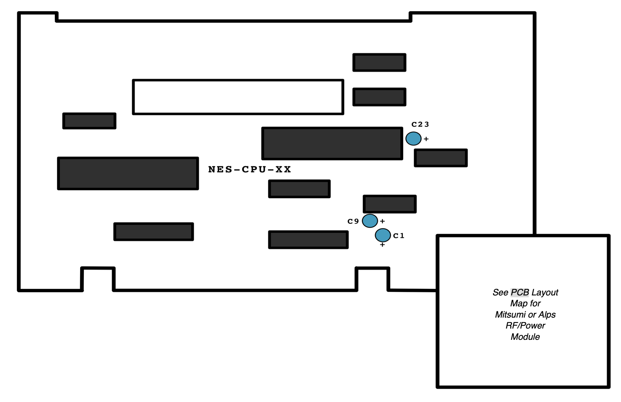
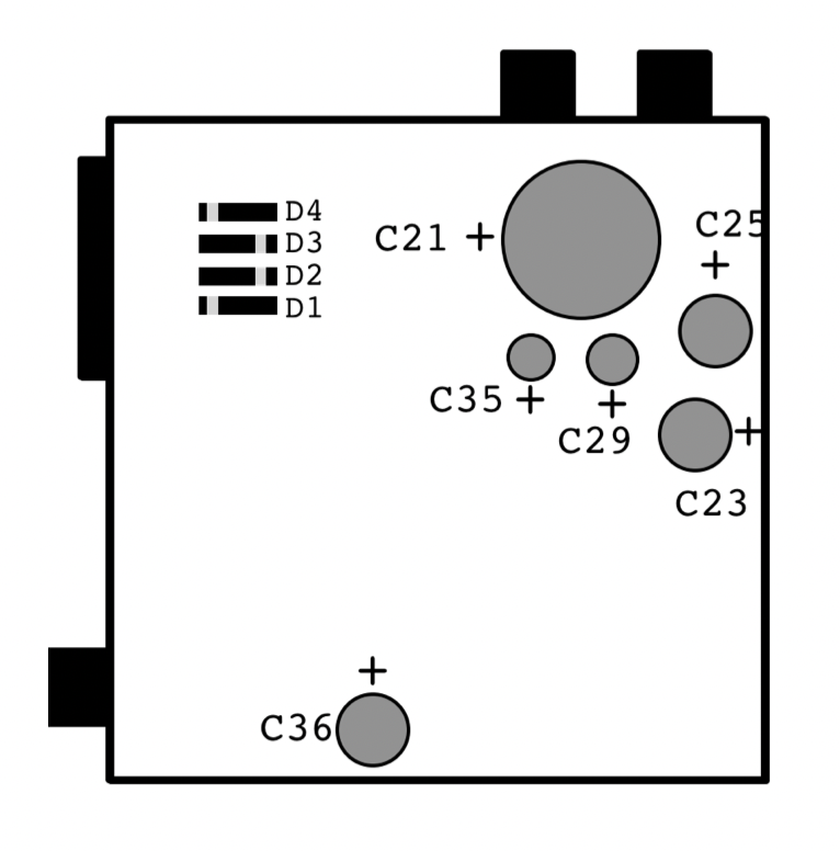
When installing new capacitors, be sure to observe the correct polarity. The longer lead indicates the positive side, which corresponds to the "+" symbol in the diagram.
| Capacitor | Location |
| 1uF 50v | C23 |
| 100uF 6.3v | C1 |
| 2.2uF 50v | C9 |
Board Layout
Mitsumi Capacitor Kit
Capacitor Guide
Capacitors play a crucial role in maintaining a steady flow of current to other components. With a typical lifespan of 20–30 years, and considering the age of most NES consoles, the original capacitors have likely reached or exceeded their expected service life. For optimal performance and reliability, replacing them is strongly recommended.
Mitsumi TDK-T31V
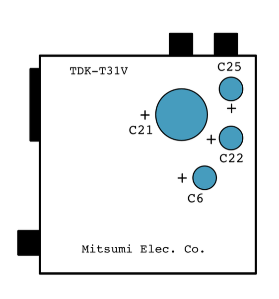 |
|
Mitsumi TDK-T12V
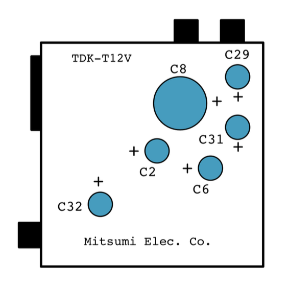 |
|
Mitsumi MTM-8V-0
 |
|
Alps Capacitor Kit (NTSC)
Capacitor Guide
Capacitors play a crucial role in maintaining a steady flow of current to other components. With a typical lifespan of 20–30 years, and considering the age of most NES consoles, the original capacitors have likely reached or exceeded their expected service life. For optimal performance and reliability, replacing them is strongly recommended.
Alps FR853
|
|
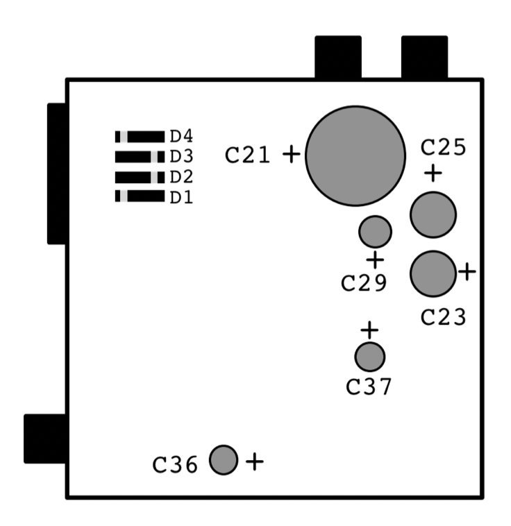
400v Diodes Locations: D1, D2, D3, D4
|
Alps SH-SH5 / FS074
|
|
400v Diodes Locations: D1, D2, D3, D4
|