Product Sheets
Designed as a convenient electronic reference for customers who have purchased a kit, these documents ensure accuracy and ease during the repair process.
- Power LED Mod Kit
- Sega Dreamcast (NTSC) Controller Port Kit (Non-Rechargeable Battery)
- Sega Dreamcast (NTSC) Controller Port Kit (Rechargeable Battery)
Power LED Mod Kit
Component Guide
5MM LED (Assorted Colors)
PCB Location: LED1
Choose the LED color that suits your style. If you're installing a new LED, make sure the longer lead (the positive/anode side) is positioned to the left, as indicated by the "+" symbol in the diagram. If you prefer to keep the original LED, mark the positive lead with a marker before removal to ensure proper orientation during reinstallation.
Take extra care when working with the power LED pads—they're delicate and can be easily damaged. Using flux and setting your soldering iron to a lower temperature can help protect the pads during both soldering and desoldering.
150 Ohm, 0.5w Resistor
PCB Location: R1
The resistor limits the amount of current flowing to the LED—the higher the resistance, the dimmer the LED will appear. If the LED you’ve chosen is too bright for your liking, you can use the included resistor to reduce its brightness. Solder the resistor in-line with the positive (longer) leg of the LED. This is an optional install and not necessarily recommended.
Keep in mind that while the board does include a resistor labeled R1, it’s designated for the battery circuit - not the LED - so it won’t affect the LED’s brightness.
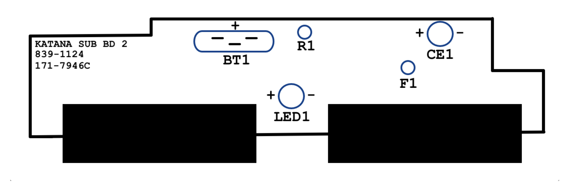
Board Layout
Sega Dreamcast (NTSC) Controller Port Kit (Non-Rechargeable Battery)
Component Guide
47uF 10v Capacitor
Location: CE1
Capacitors keep a consistent flow of electricity to other components. They typically have a lifespan of 20 - 30 years and given the age of most Dreamcasts it is recommended to replace the capacitor now as preventive maintenance. Be sure to install the capacitor in the correct polarity with the longer lead facing toward the positive direction.
72v 400mA Resettable Fuse
Location: F1
Fuses are safety devices that prevent unsafe current from reaching vital components of your Dreamcast. Included with this kit is an upgraded “resettable” fuse. If the fuse ever blows it can be reset by leaving the Dreamcast unplugged for a few seconds without the need to replace the fuse.
Coin Cell Battery Holder
Location: BT1
The factory CMOS battery is soldered to the PCB and is not easily replaceable. This upgrade allows for future replacements of the CMOS battery without the need for soldering.
13 Ohm 0.5w Resistor
Location: R1
Resistors typically have a very long lifespan. It is included in this kit as an optional replacement.
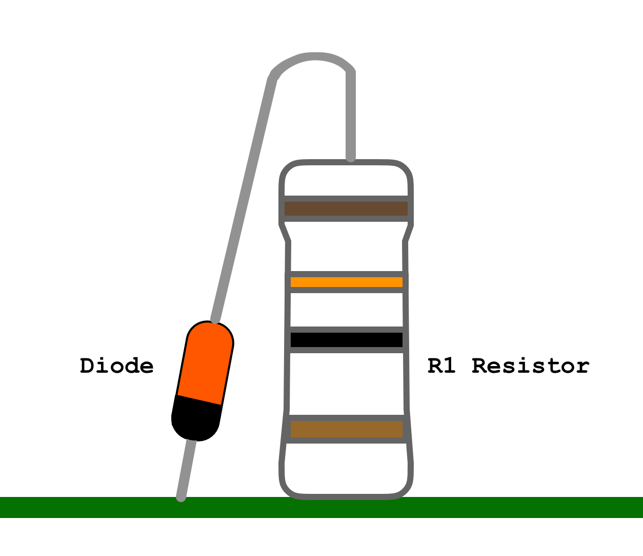
Schottky Diode
Location: R1
Since this kit is intended to be used with a non-rechargeable battery, a “Schottky” diode is used to prevent electrical current from reaching the battery and causing damage.
The diode will be installed attached to the resistor found at R1. Cut the top lead of the resistor to attach the diode as seen in the diagram. Be sure the cathode/negative end (the black stripe) is facing down toward the board.
Diagrams
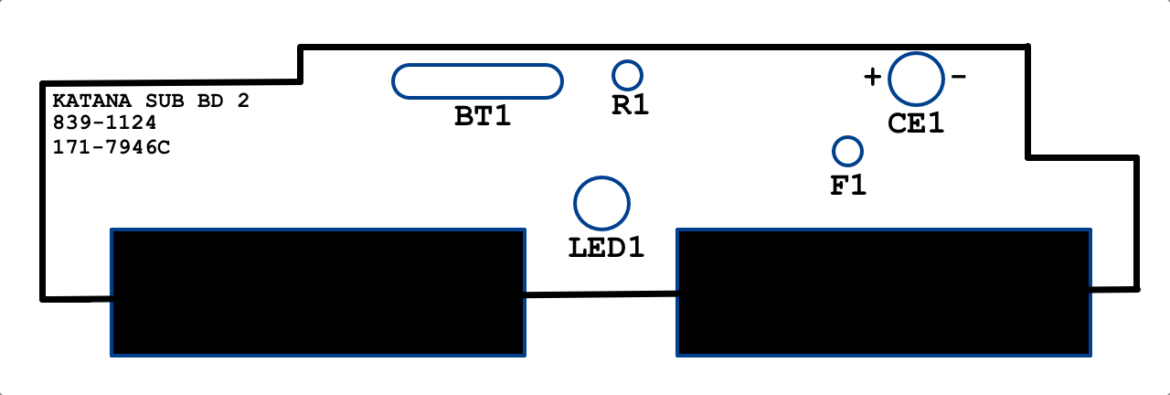
Sega Dreamcast (NTSC) Controller Port Kit (Rechargeable Battery)
Component Guide
47uF 10v Capacitor
Location: CE1
Capacitors keep a consistent flow of electricity to other components. They typically have a lifespan of 20 - 30 years and given the age of most Dreamcasts it is recommended to replace the capacitor now as preventive maintenance. Be sure to install the capacitor in the correct polarity with the longer lead facing toward the positive direction.
72v 400mA Resettable Fuse
Location: F1
Fuses are safety devices that prevent unsafe current from reaching vital components of your Dreamcast. Included with this kit is an upgraded “resettable” fuse. If the fuse ever blows it can be reset by leaving the Dreamcast unplugged for a few seconds without the need to replace the fuse.
Coin Cell Battery Holder
Location: BT1
The factory CMOS battery is soldered to the PCB and is not easily replaceable. This upgrade allows for future replacements of the CMOS battery without the need for soldering.
After replacing the ML2032 battery, it is recommended to leave your Dreamcast powered on for 1 to 2 hours to allow the battery to charge.
13 Ohm 0.5w Resistor
Location: R1
Resistors typically have a very long lifespan. It is included in this kit as an optional replacement.
Diagrams