Sega Dreamcast
The Sega Dreamcast, released in 1999, was Sega’s final home console and the first of its generation to include a built-in modem for online play. It features a Hitachi SH-4 CPU, PowerVR2 GPU, and a unique VMU (Visual Memory Unit) for storage and display. This section covers hardware revisions, common failure points (like PSU and GD-ROM drive issues), and repair/modding techniques
- Product Sheets
- Power LED Mod Kit
- Sega Dreamcast (NTSC) Controller Port Kit (Non-Rechargeable Battery)
- Sega Dreamcast (NTSC) Controller Port Kit (Rechargeable Battery)
- General Information
Product Sheets
Designed as a convenient electronic reference for customers who have purchased a kit, these documents ensure accuracy and ease during the repair process.
Power LED Mod Kit
Component Guide
5MM LED (Assorted Colors)
PCB Location: LED1
Choose the LED color that suits your style. If you're installing a new LED, make sure the longer lead (the positive/anode side) is positioned to the left, as indicated by the "+" symbol in the diagram. If you prefer to keep the original LED, mark the positive lead with a marker before removal to ensure proper orientation during reinstallation.
Take extra care when working with the power LED pads—they're delicate and can be easily damaged. Using flux and setting your soldering iron to a lower temperature can help protect the pads during both soldering and desoldering.
150 Ohm, 0.5w Resistor
PCB Location: R1
The resistor limits the amount of current flowing to the LED—the higher the resistance, the dimmer the LED will appear. If the LED you’ve chosen is too bright for your liking, you can use the included resistor to reduce its brightness. Solder the resistor in-line with the positive (longer) leg of the LED. This is an optional install and not necessarily recommended.
Keep in mind that while the board does include a resistor labeled R1, it’s designated for the battery circuit - not the LED - so it won’t affect the LED’s brightness.
Board Layout
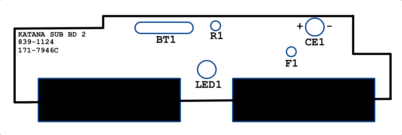
Sega Dreamcast (NTSC) Controller Port Kit (Non-Rechargeable Battery)
Component Guide
47uF 10v Capacitor
Location: CE1
Capacitors keep a consistent flow of electricity to other components. They typically have a lifespan of 20 - 30 years and given the age of most Dreamcasts it is recommended to replace the capacitor now as preventive maintenance. Be sure to install the capacitor in the correct polarity with the longer lead facing toward the positive direction.
72v 400mA Resettable Fuse
Location: F1
Fuses are safety devices that prevent unsafe current from reaching vital components of your Dreamcast. Included with this kit is an upgraded “resettable” fuse. If the fuse ever blows it can be reset by leaving the Dreamcast unplugged for a few seconds without the need to replace the fuse.
Coin Cell Battery Holder
Location: BT1
The factory CMOS battery is soldered to the PCB and is not easily replaceable. This upgrade allows for future replacements of the CMOS battery without the need for soldering.
13 Ohm 0.5w Resistor
Location: R1
Resistors typically have a very long lifespan. It is included in this kit as an optional replacement.
Schottky Diode
Location: R1
Since this kit is intended to be used with a non-rechargeable battery, a “Schottky” diode is used to prevent electrical current from reaching the battery and causing damage.
The diode will be installed attached to the resistor found at R1. Cut the top lead of the resistor to attach the diode as seen in the diagram. Be sure the cathode/negative end (the black stripe) is facing down toward the board.
Diagrams

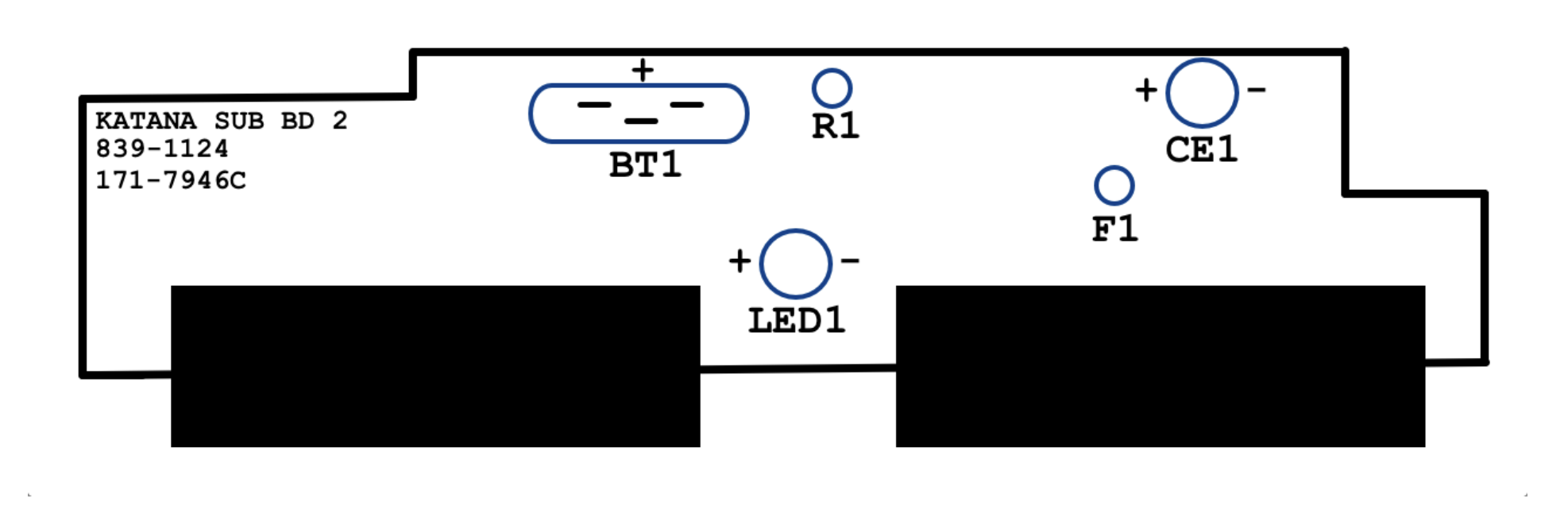
Sega Dreamcast (NTSC) Controller Port Kit (Rechargeable Battery)
Component Guide
47uF 10v Capacitor
Location: CE1
Capacitors keep a consistent flow of electricity to other components. They typically have a lifespan of 20 - 30 years and given the age of most Dreamcasts it is recommended to replace the capacitor now as preventive maintenance. Be sure to install the capacitor in the correct polarity with the longer lead facing toward the positive direction.
72v 400mA Resettable Fuse
Location: F1
Fuses are safety devices that prevent unsafe current from reaching vital components of your Dreamcast. Included with this kit is an upgraded “resettable” fuse. If the fuse ever blows it can be reset by leaving the Dreamcast unplugged for a few seconds without the need to replace the fuse.
Coin Cell Battery Holder
Location: BT1
The factory CMOS battery is soldered to the PCB and is not easily replaceable. This upgrade allows for future replacements of the CMOS battery without the need for soldering.
After replacing the ML2032 battery, it is recommended to leave your Dreamcast powered on for 1 to 2 hours to allow the battery to charge.
13 Ohm 0.5w Resistor
Location: R1
Resistors typically have a very long lifespan. It is included in this kit as an optional replacement.
Diagrams
General Information
The Sega Dreamcast, released in late 1998 in Japan and 1999 in North America and Europe, was Sega’s final home console and a technically advanced system for its time. It featured a custom Hitachi SH-4 RISC processor running at 200 MHz and a PowerVR2 CLX2 GPU capable of hardware transform and lighting, supporting a maximum resolution of 640x480. The system included 16 MB of main RAM, 8 MB of video RAM, and 2 MB of audio RAM. Its audio was powered by a Yamaha AICA sound processor with a built-in ARM7 CPU, providing 64 hardware channels and advanced effects processing.
One of the Dreamcast’s standout features was its built-in 56K modem (or optional broadband adapter), enabling online multiplayer gaming and web browsing, an industry first for consoles at the time. It used proprietary GD-ROM discs capable of storing up to 1.2 GB of data, which offered more capacity than standard CDs but less than DVDs used by later systems. Hardware-wise, the Dreamcast is known for its modular internal design, making it relatively easy to disassemble and service. Common hardware issues include power supply failure, GD-ROM drive read errors, and controller port fuse problems. The console also featured the VMU (Visual Memory Unit), a unique memory card with its own screen, buttons, and micro controller, capable of running mini-games and displaying in-game data. The Dreamcast remains a favorite among modders and enthusiasts due to its accessible architecture, strong homebrew scene, and support for VGA output and optical drive emulators (ODEs) like GDEMU.
Hardware Specifications
- CPU: Hitachi SH-4 (200 MHz, 32-bit RISC)
- GPU: PowerVR2 CLX2 (100 MHz, 3 million polygons/sec, hardware T&L)
- RAM:
- 16 MB main system RAM
- 8 MB video RAM
- 2 MB audio RAM
- Storage Media: GD-ROM (1.2 GB capacity per disc)
- Audio: Yamaha AICA sound processor with ARM7 (32-bit, 45 MHz)
- Video Output: Composite, S-Video, RGB SCART, VGA (via adapter)
- Expansion:
- 56K Modem (RJ11)
- Optional Broadband Adapter (LAN)
- Controller ports (x4) with VMU support
- Power Supply: 100–240V AC internal PSU (frequently fails due to heat)