Power LED Mod Kit
Component Guide
5MM LED (Assorted Colors)
PCB Location: LED1
Choose the LED color that suits your style. If you're installing a new LED, make sure the longer lead (the positive/anode side) is positioned to the left, as indicated by the "+" symbol in the diagram. If you prefer to keep the original LED, mark the positive lead with a marker before removal to ensure proper orientation during reinstallation.
Take extra care when working with the power LED pads—they're delicate and can be easily damaged. Using flux and setting your soldering iron to a lower temperature can help protect the pads during both soldering and desoldering.
150 Ohm, 0.5w Resistor
PCB Location: R1
The resistor limits the amount of current flowing to the LED—the higher the resistance, the dimmer the LED will appear. If the LED you’ve chosen is too bright for your liking, you can use the included resistor to reduce its brightness. Solder the resistor in-line with the positive (longer) leg of the LED. This is an optional install and not necessarily recommended.
Keep in mind that while the board does include a resistor labeled R1, it’s designated for the battery circuit - not the LED - so it won’t affect the LED’s brightness.
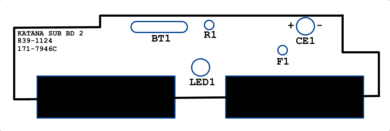
Board Layout
No Comments